November 2019
Materials graph tutorial – Lens Studio
Lens Studio has been updated to v2.3, and I personally think this is one of its most important updates to date.
The key new feature is the Shader Graph Editor – I got to play around with the beta for a while, and on this page I am sharing my research and basic setups to give you a head start.
My goal will be to demystify the Shader Graph, so you can start playing around in it without having the feeling like things are getting too complicated.
I’m starting off with a basic introduction, then it gets more technical, and at the end you’ll find a long list of downloads to learn from!
For a video tutorial, see Ben Knutson’s Shader Graph Introduction on youtube!
I also did a more technical talk on materials at Lens Fest, check it out here.
Introduction to the Shader Graph Editor
I will get to the Shader Graph Editor in a few steps, but it’s good to see how to get there first.
We’re going to build our own Post Effect in the Shader Graph editor, so we first need to have the basic Post Effect setup.
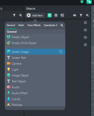
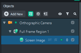
Make a “Screen Image” object in your Scene, and delete everything else:
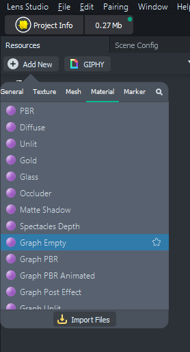
Then, add a ‘Graph Empty’ material to your Resources.
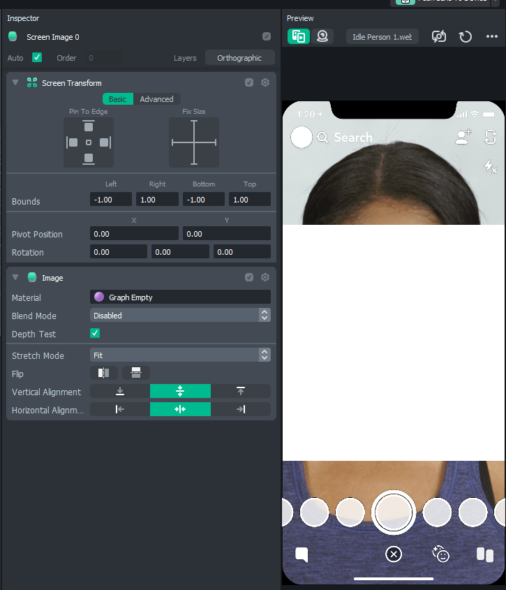
If you drag this new material in the Screen Image’s ‘Material’ in the Inspector, it will show up with no options at all. You can’t even choose a texture.
And it only outputs a white color. This is a completely empty material right now.
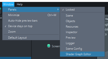
To give this material something to do, go to Window > Panels > Shader Graph Editor.
A new window will pop up. Make it full screen, that’s the easiest way to keep oversight when working in this editor.
You’ll see this material is not entirely empty – there already is a “Shader” node in it. A ‘node’ is one of these blocks you can drag around in the graph:
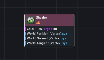
All materials have this Shader node.
You should place your nodes from left to right, so they connect to this Shader node at the end!
Let’s build something really simple. For instance, we want to make the material display a texture we can choose in the Inspector.
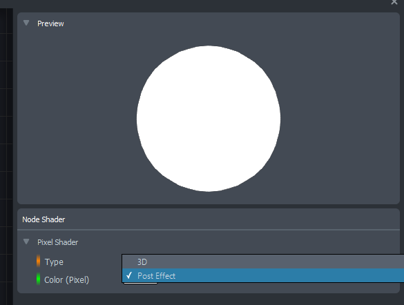
First, the Shader node needs to be set to “Post Effect” – click on it, then change the value in the list on the right side of the screen. This will tell Lens Studio this material is not for 3D objects, but for Post Effects.
(I will get to 3D shaders later.)
Now we need the texture. This is where we are actually going to lay down the first node! Press TAB to add a new node, and search for “Texture 2D Parameter”. Place it somewhere in your graph.
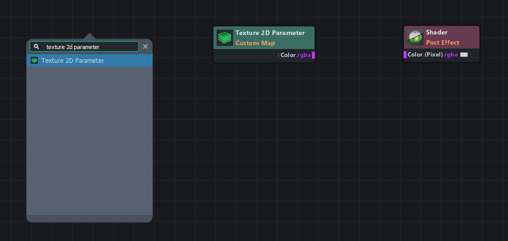
As you can see, the Texture node has a purple square on the right side (with the text ‘Color.rgba’), and the Shader node has one on the left side. If you click and drag one of the squares, you can connect it to the other.
This explains the most important part of what nodes do:
a node is a block that takes information (in this case a Color for each pixel, from the texture), it then does something with that information, and exports it for another node to use.
Make sure you always know what kind of information you’re putting into a node, and what you’re getting as a result!
In this case, the Texture 2D Parameter has the word “Parameter” in the name, which means it gets its information from the user through the Inspector panel.
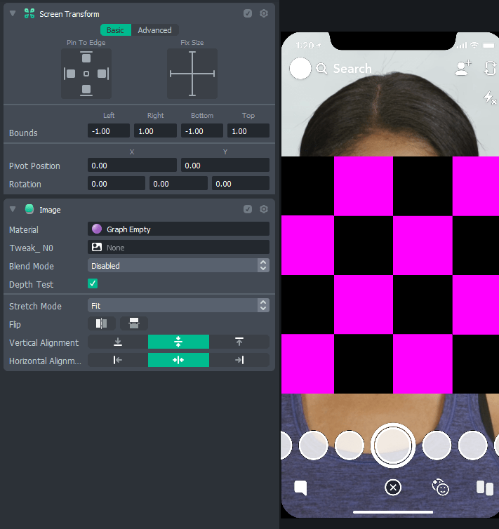
If you look at the Screen Image back in your project panel, you’ll see there now is an option to add a texture!
By default, if there is no Texture added, this purple/black checkerboard is shown. But you can add any texture to this material you like.
Add the Device Camera Texture, for instance, to get the camera input in your shader!
As you can see when scrolling through the TAB list in the Graph Editor, there are a lot of nodes to choose from.
Most are simple mathematical operations (like Multiply or Add).
They take information, do some mathematical operation on it, and pass it through to the next node.
“Information”, in this context, means a number. So the color red will be represented by a number (between 0 and 1 – 0 for no red, and 1 for 100% red),
and the same goes for green and blue.
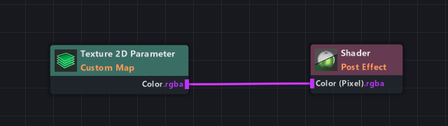
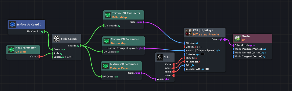
This is what we’ve got so far: a texture, directly hooked up to a Shader node set to Post Effect.
This gets the texture color information from the Inspector panel, and outputs that as the shader. That’s not very interesting.
The texture data is RGBA data – which is just 4 numbers: Red, Green, Blue, Alpha (=transparency).
Since they’re just numbers, you could multiply this texture by another number, which will change the brightness of the image.
Add a Multiply node to this graph. You can hold shift and drag it on top of the line to make it connect automatically.
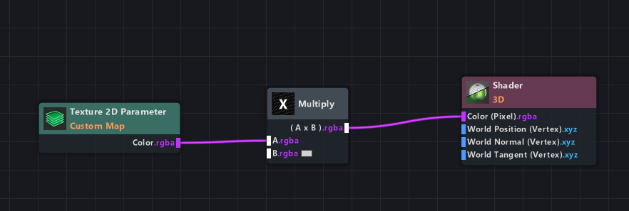
This node multiplies by 1 by default, which means nothing changes. (Don’t worry, this is as mathematical as this tutorial will get.)
Now, add a Float Parameter node. The Float Parameter is a node that generates a number. The number can be chosen by the user from the Inspector panel.
All “Parameter” nodes are green, which is an easy indicator that these get their information from the Inspector panel.
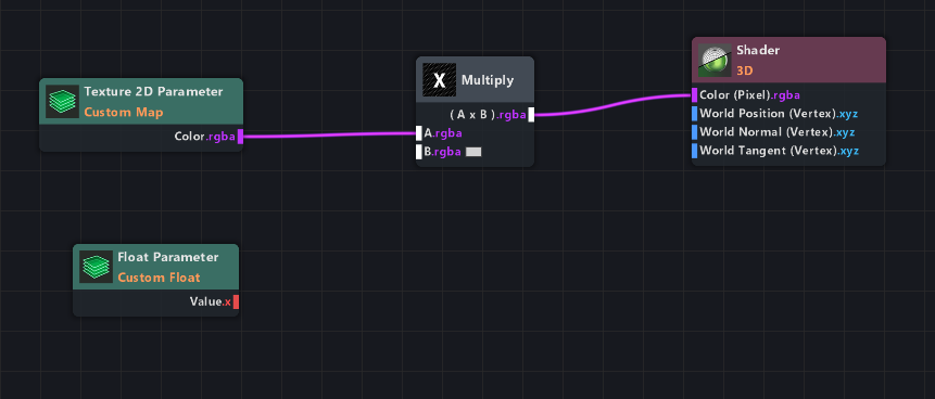
Maybe you have already noticed that this Float Value node only outputs a data type called ‘x’ (and it is red instead of purple). Fortunately, Lens Studio doesn’t mind different types of data.
If you multiply it, it will simply convert it or change the input of the node. In this case, it is changing the input of the Multiply node as soon as you connect it (notice how it changed from B.rgba to B.r in the Multiply node when you connect it).
It does not matter that the line is going from ‘x’ to ‘r’, by the way. They are both just one channel of information, and the letter makes no difference to how it is calculated.
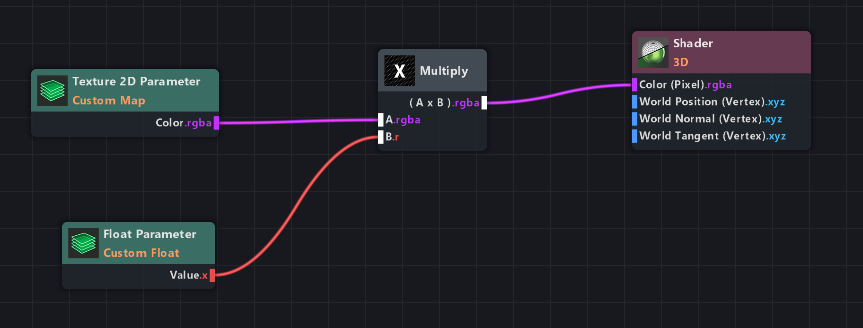
So what does this setup do?
It multiplies all channels of the first input of the Multiply node (r, g, b, a) with the single channel of the second input.
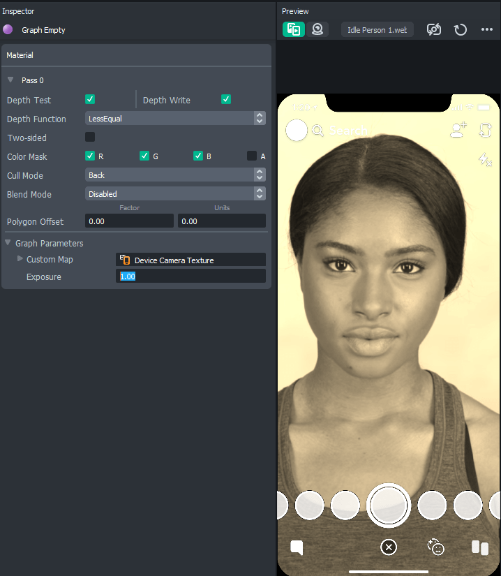
Click on the Float Parameter node and change its Title on the right side of the screen so you can find it in the Inspector.
I called it ‘Exposure’.
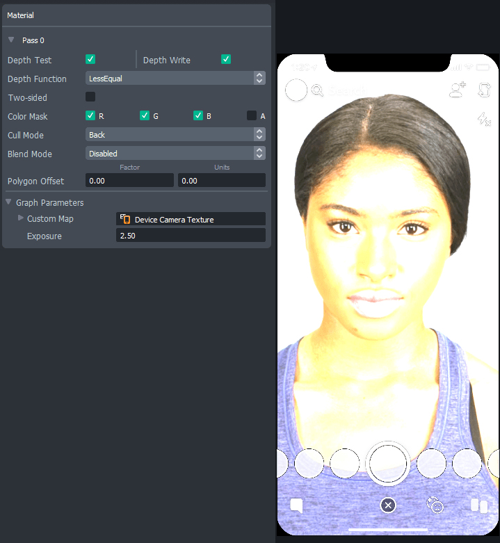
When you click on the material in your Resources panel back in your project, you will actually see this ‘Exposure’ value with a custom number next to it! This will now change how bright the shader is.
In my case, I added the shader to a Screen Image component in the Scene, and then used the Device Camera Texture as Texture input.
What’s happening here is that each pixel gets a value from the Texture, and that value is then multiplied by your number (which changes its exposure). And that resulting value is shown in this Post Effect.
See Accessing materials through JavaScript if you want to change this exposure value with your own script!
Some nodes have complete effects built-in already, like the Sepia node. If you replace the Multiply node with that one (and hook up the Float Parameter to the Sepia’s Amount input), it will instantly give you the sepia colors of the Texture (and you can still use the Exposure parameter to change it! Maybe change the title of that Float Parameter to “Sepia Amount”).
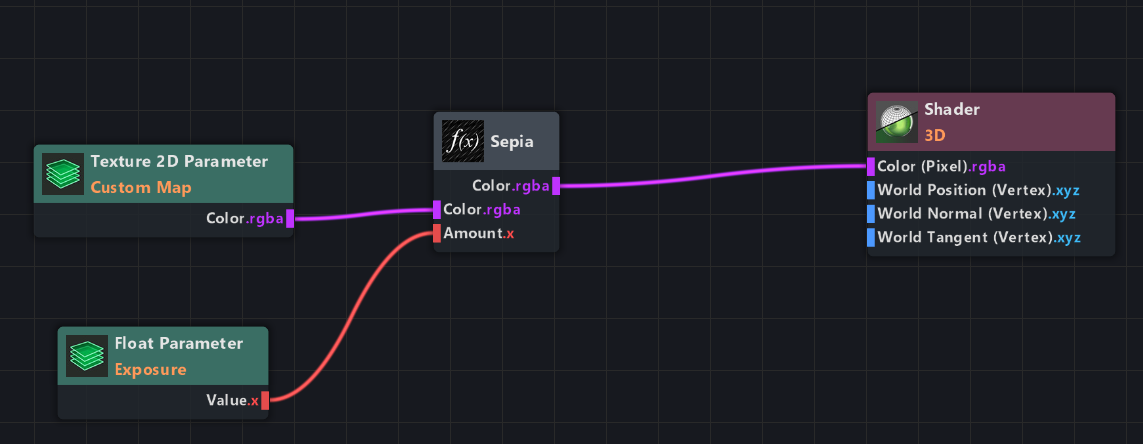
This example project can be downloaded all the way at the bottom of the page. I did make it a bit more advanced, so go check it out and see if you can figure out how it works!
Accessing materials through JavaScript
All green ‘Parameter’ nodes in the Shader Graph can be accessed using code! Which is great, because you can use that to animate your materials, or make them interactive.
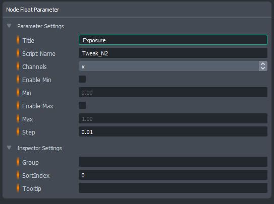
If you want to access a float value in your material with the title “Exposure”, make sure you know the “Script Name” value for the parameter node (which is right below its “Title” value).
This is where you can find the Script Name:
So in this case the Script Name is set to “Tweak_N2”. You can change that to something more readable, like “ExposureValue”!
Then, you can then get/set its value with this code, where “ExposureValue” is the Script Name of the Float Parameter. This will set it to a value of 5:
|
0 1 2 |
//@input Asset.Material YourMaterial script.YourMaterial.mainPass.ExposureValue = 5; |
The only input required for this script is the material itself
You can also get the material from a Mesh Visual component like so:
|
0 1 2 |
//@input Component.MeshVisual MeshWithGraphShader script.MeshWithGraphShader.mainPass.ExposureValue = 5; |
To animate it, the easiest way that does not require any maths would be to use Tweens!
You can use the Tween Value script (or multiple, using the Tween Chain), and apply its resulting value to the material.
This ‘Balloonify’ material is a good example of how Tweening helps make things look smooth:
To download the project files for this one or for other Shader Graph examples, see the downloads down below!
Vertex displacement
Displacement
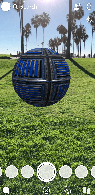
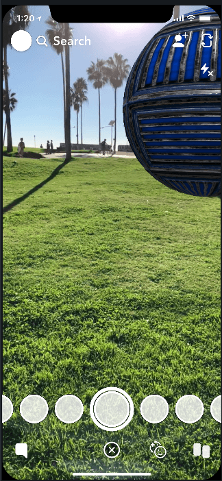
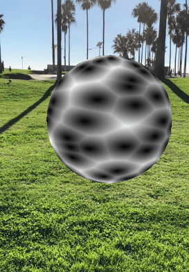
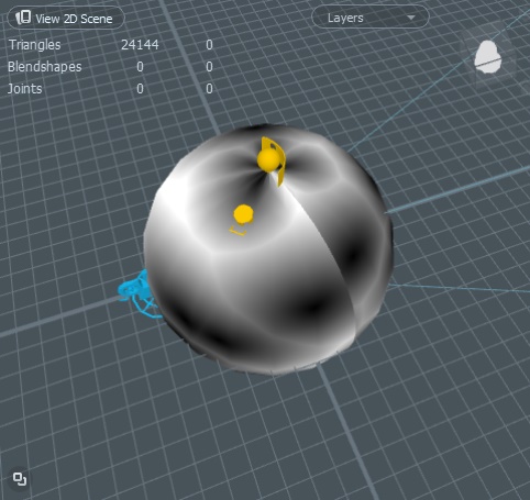
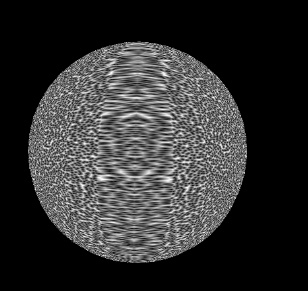
Vertex displacement is the best. It lets the Shader drive the position of each vertex on the mesh, which can give you this kind of result (this is a sphere!)
I’m going to start with a demonstration. We’ll be making a wobbly sphere, like the example above.
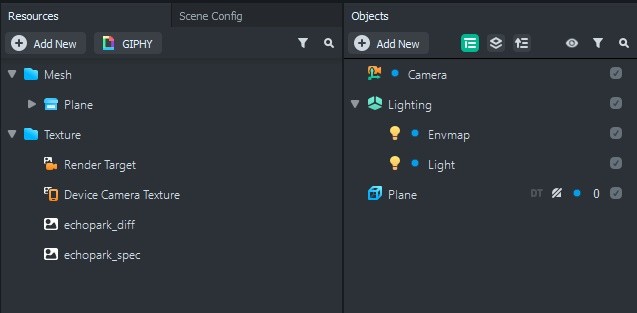
Make a sphere in your scene, and add a “Graph PBR” material to it (which you can make in the Resources panel).
The Graph PBR is simply a preset of a Shader Graph material that already has the right nodes for the main textures, so we can skip the boring stuff and get straight to displacement.
You should start off with this preset of a sphere:
Open up the Shader Graph panel. Move all the texture stuff out of view – we need some space to work. Do keep it connected, though.
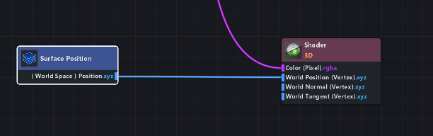
As you can see in the Shader node, there also is a World Position (Vertex) input. That’s what we’re going to be working with.
Since these are absolute world position values, it means the values are not relative to the mesh. For instance, giving it a value of 0 will make the object invisible (since all vertices will then be at the same position: [0, 0, 0]).
To make the mesh wobble, we will need the current vertex position first. The wobble needs to be added on top of that.
You can get the current vertex world positions with the node called ‘Surface Position’. Connect it to the World Position input in the Shader node, and nothing will change. Which makes sense – you’re giving it the same information it already had.
Now we can add any values to this Surface Position we like!
For instance, if you make an Add node, connect it to this line, and connect an ‘Elapsed Time’ node to the second input of the Add node:
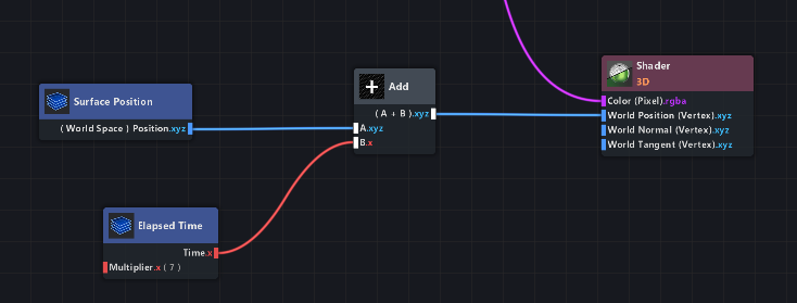
The sphere will now slowly move up, to the right and towards you. In a diagonal direction. Change the Multiplier parameter in the Elapsed Time node to make it go faster or slower.
How does this work? And why is it moving diagonally?
The Surface Position data has 3 dimensions: x, y, and z. If you add one-dimensional data from a node like the Elapsed Time node (which outputs only a number) to all of those values, they will all go up.
A positive number on the X-axis is going to the right, one on the Y-axis is moving up, and one on the Z-axis is pointing towards you.
If you get all three at once, it means it will diagonally point in the combined direction of up, right, and towards you.
So to make it move away, to the left, and downwards, diagonally, you’d simply have to multiply the Elapsed Time node by -1.
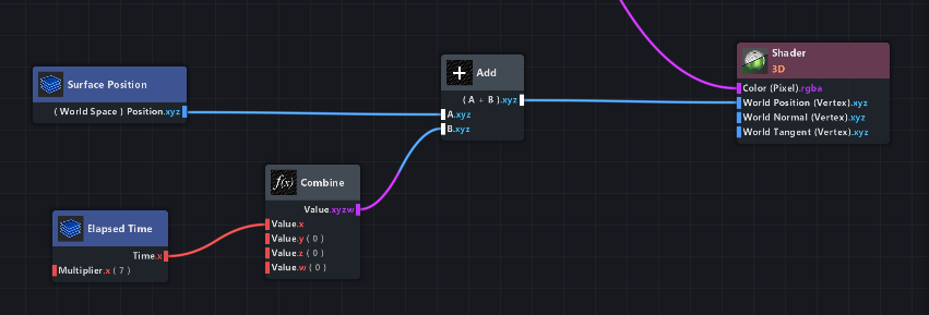
If you want it to move on the X axis only (left to right), you could add a ‘Combine’ node between the Elapsed Time and the Add.
Only connect it to the x input of the Combine, so the y and z will stay at 0. (The ‘w’ input can be ignored for now.)
This way, only the X-axis will receive that value from Elapsed Time. The other two will remain at their original position!
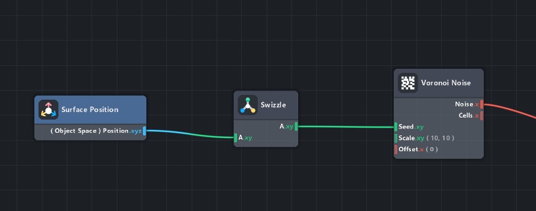
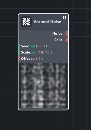
Now we’re going to generate that wobbly randomness, using a Voronoi Noise.
The Voronoi Noise node generates a random pattern, based on the seed you give it. In the case of 3D models, you can give it the UV map of the model!
Temporarily connect the Voronoi Noise node to the Shader color input – that way you can see what’s happening.
Also, connect the Seed input to a ‘Surface UV Coord’ node, which gives the object’s UVs.
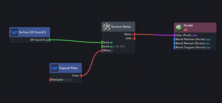
That’s looking pretty good. You can even connect that Elapsed Time node to the Offset input of the Voronoi Noise, so it will be animated!
We will be using this in the Vertex Displacement later. But for now, let’s keep it visible by having it connected to the Shader color.
The next step in making a wobbly sphere is making this noise work in both directions.
We want the wobbles to go inwards and outwards the sphere, which means the noise values will have to go into negatives as well.
Right now, as is the default, the Voronoi Noise is only giving values between 0 and 1 (black and white). We want it to be -1 to 1, so it moves in both directions.
To remap those values, simply add a Remap node and set it to Range In: 0 to 1, and Range Out: -1 to 1.
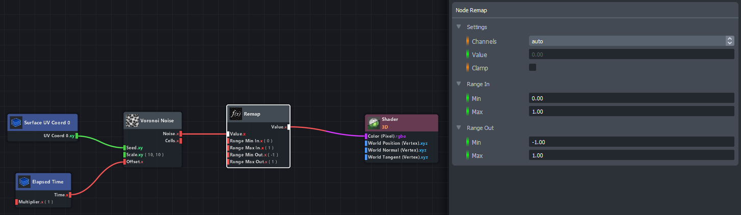
Now, the noise is ranging from -1 to 1, which we can’t really see in the Preview, since 0 and everything below it is shown as black.
Let’s reconnect the PBR node that was already there to the Shader color input.
Then, add that Surface Position node to the output of the Remap node using an Add node (so the noise is added to the mesh), and connect that result to the World Position (Vertex) input of the Shader node!
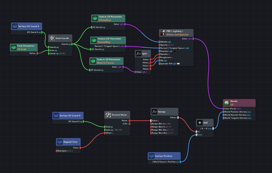
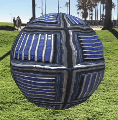
The result in the preview is barely visible, but it is there. To make it more extreme, add a Multiply node with any higher value in it (I use 30) directly after the Remap node (before the Add node):
Now you can really see some animated displacement!
The last thing we need to do, is to get rid of that diagonal direction in the displacement.
This is, like with the example I showed earlier, caused by having the same value added in all three axes. In this case, that value is the Voronoi noise.
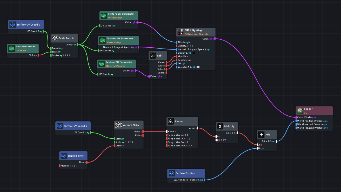
It is the same in all three directions, so let’s create three different versions for it!
Copy the Voronoi Noise two more times, and connect the Surface UV node and Time Elapsed nodes that were already there to those new ones as well.
Next, we’re going to need some variation. For the second Voronoi Noise, place an Add node between it and the Elapsed Time node. Enter some large value (like 1000).
Now do the same for the third noise, but make it even larger (2000).
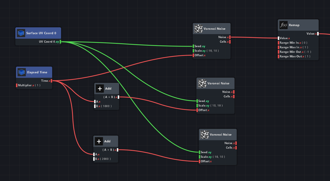
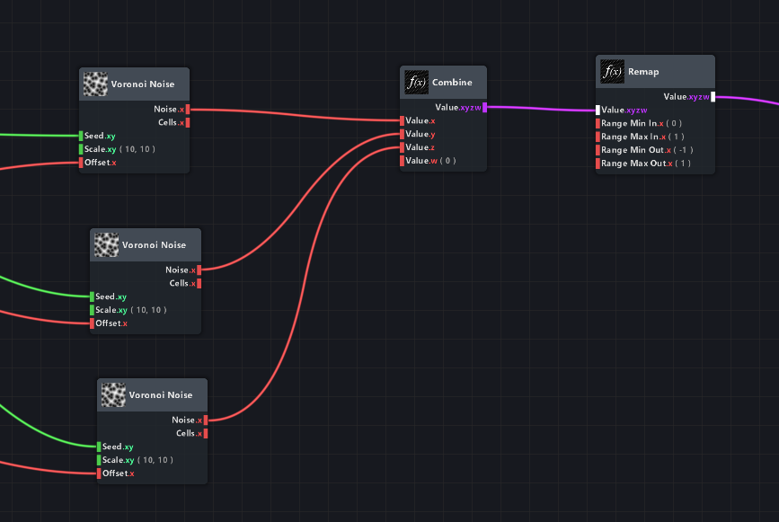
All three noises will now be different values, but how do you join them together into one stream of data that we can plug into the Remap node?
That’s what a ‘Combine’ node is for. Plug all values in their respective input in the Combine, and you’ve got it bundled up for Remapping. And that’s it!
(This is a basic version of what’s going on in that ‘Triplanar Noise’ subgraph you can find in the preset materials from the Material Library!)
You can actually preview this noise, which is a cool looking effect in itself. Temporarily connect the output of the Combine node to the Color input of the Shader node, and you’ll see a colorful, animated texture.
I turned down the value in the Multiply node a bit, too, just to make it look better.
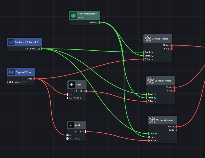
Now that the displacement works, we want it to be more customizable! For example, the Scale input (xy) in the Voronoi Noise nodes should be exposed in the Inspector, so you can play around with the scale.
To do that, add a Float Parameter and set it to Channels: xy, Title: scale,
and connect it to all three Scale inputs of the Voronoi nodes. You can now change the noise scale from the Inspector!
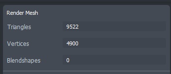
Keep in mind that this Lens Studio default Sphere object only has a certain amount of vertices in it – if you want a higher resolution for displacement, you’ll have to make your own sphere mesh in a 3D software.
(Or download my high res Sphere object down below.)
A good exercise would be to try and make another parameter that gives you the option to set the overall noise displacement amount!
It’s not a very difficult challenge, but it’s a good check to see if you understand how this works. I have added this parameter to the download for this project file down below!
In this download, the Sphere mesh is also of a much higher resolution to make the distortion more visible. This mesh can be downloaded separately at the bottom of the page, too.
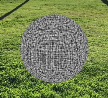
This distortion method is fine for most meshes, but if you are working with a sphere, you will see a hard line in your displacement (depending on the scale of the noises):
To learn about why this is happening – and how you can fix it – check out the section Triplanar noise & Voronoi on spheres.
In that section, I will explain what the Triplanar Noise subgraph does, and I will demonstrate how to make your own version of it that uses Voronoi noises.
It will be slightly more technical, so you’ll need to understand this section first before diving into that.
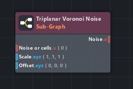
This new Triplanar Voronoi subgraph is included as a material in the download for this wobbly sphere!
This is what the seamless, more organic Triplanar Voronoi noise looks like:
Please keep in mind that there are many ways to get a cool looking distortion effect. You don’t have to closely follow this tutorial – in fact, in the case of a spherical mesh, it is probably better to not have three different Voronoi Noises and instead multiply one noise value by the Surface Normal directions!
This way, the mesh will still be wobbly, but only in the direction of the normals. Which makes it look more like it’s boiling and less like it’s just randomly moving around.
You could also use a Simplex noise instead of Voronoi, which will give you a result closer to the ‘Jello’ material in Lens Studio’s Material Library. Or use your own noise textures!
There are always many routes you can take :)
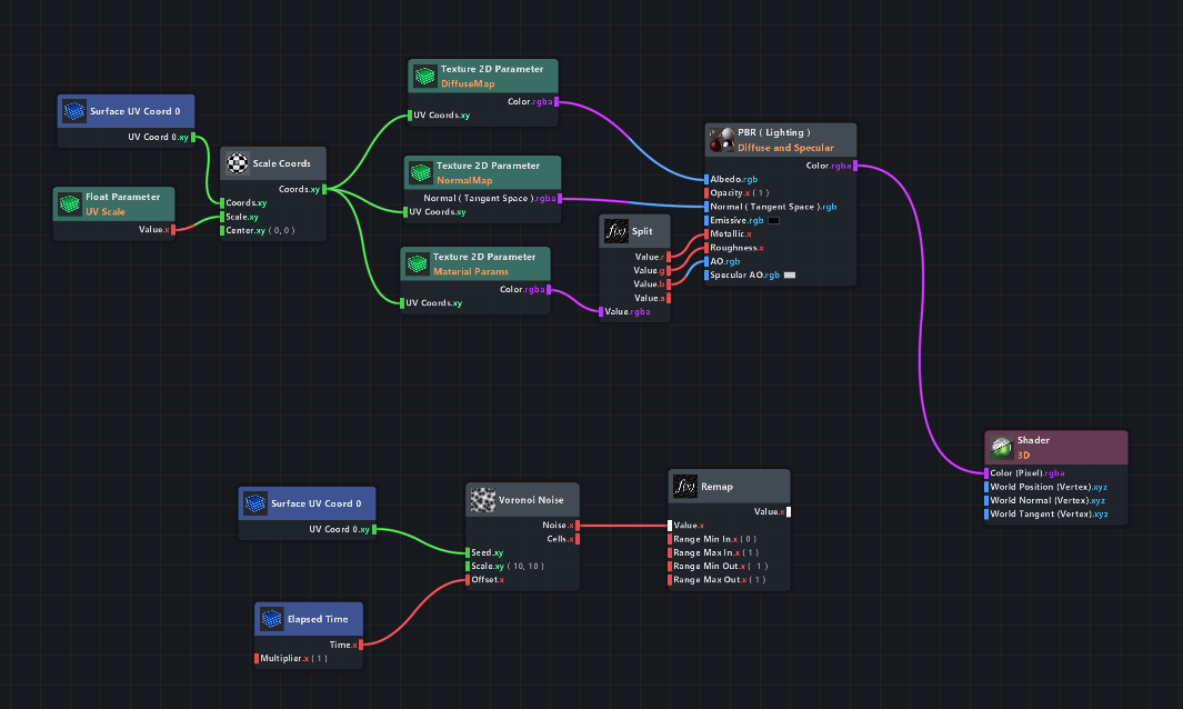
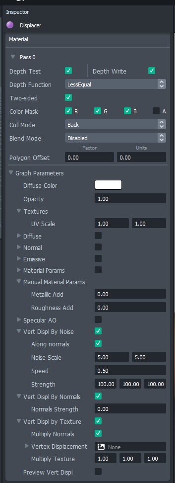
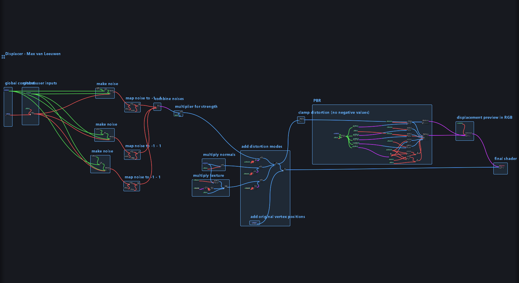
I have made an example PBR Graph Editor material that you can download at the bottom of this page,
it’s called ‘Displacer’, and it is like a standard PBR material except it has a bunch of Vertex Displacement options in it.
Opening it in the Shader Graph is a great way to learn if you’re new to it.
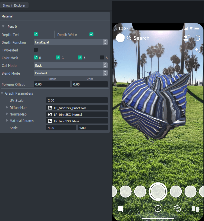
This is what Displacer’s material options look like:
All parameters in this material are easily accessible via script. Using a simple script to modify the Distortion along Normals could, for instance, be used to make this ‘balloonify’ setup (project file download at the bottom of the page):
Projections
And now for something completely different: projection distortion.
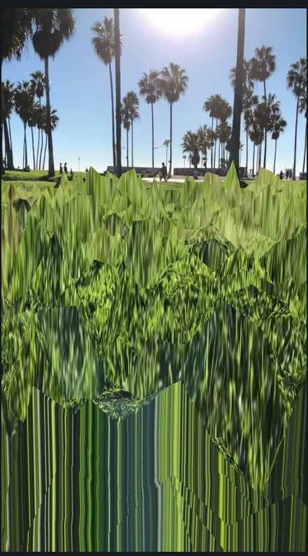
I will be demonstrating how to make the following surprisingly simple effect
(project files can be downloaded at the bottom of this page).
This effect is setup the following way:
First, there’s a plane with a high vertex count.
The Device Camera Texture (the video coming from the user’s phone) is then ‘projected’ onto that surface, from the perspective of the camera.
Then, the plane is distorted while still having this texture on it, and rendered on top of the camera input.
Let’s start with step 1! Go get that high resolution geometry. The default Lens Studio plane is not good enough, since it only has 4 vertices. We’ll need something closer to this:
Make one yourself in a 3D software, or get it from the download for this demo down below!
Now, to set up the scene, add the Plane object and add a Device Camera Tracker to the camera.
You should see the purple checker board on the ground at this point.
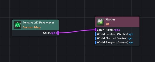
Next up, we’re going to make an Empty Graph material and give it a Texture node. Connect the Texture node to the Shader.
If you then apply this material (I called it ‘Distortion’) to the plane, you can give the plane a texture.
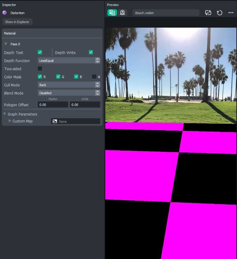
Sadly, though, when you apply the Camera Device Texture to this Texture input, the camera input is not properly skewed. It looks like this:
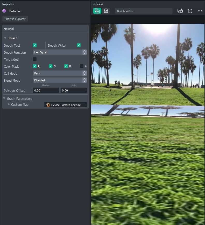
Which makes sense – it’s just displaying the camera texture as a flat image on the plane.
We want it to be projected (‘beamed’) from the virtual camera position from where we’re looking at it.
So, on every frame, the Plane should update its UVs to make the texture seem flat and aligned to the phone screen, when looked at it from the virtual camera’s perspective.
This little bit of code can do that:
|
0 1 2 3 |
//@input Component.MeshVisual plane //@input Component.Camera cam script.plane.snap(script.cam); |
Just put this in a Script file and place that on your Plane object.
You then have to select the Mesh Visual called ‘plane’ and the Camera called ‘cam’ for it to work, but this should not be too difficult since there is only one of each in your scene.
Set this script to ‘Frame Updated’, and the plane will seem to disappear!
It did not actually disappear, but its texture is exactly the same as what’s behind it. So you don’t see it. If you don’t believe that, you can temporarily set the script to ‘Tapped’ and see how it actually updates its camouflage when you tap the screen!
Now we can go ahead and distort this plane using the Shader Graph!
Keep in mind that there are a billion different and cool kinds of effects you can make with this,
so this tutorial is giving you more of a head start than an actual final result.
Just a quick introduction to vertex displacement: there’s X, Y, and Z information going in that Shader node, and all three are just numbers.
I only want the Y number to change, because Y is the up/down axis and I want that to happen for the distortions.
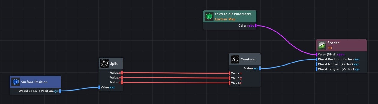
To demonstrate what changing the Y value does, place a Surface Position node and connect it to the Shader.
Now, split it and recombine it again. This will give you control over all three axis separately.
You could now add an Add node to the line of the Y-axis, and enter some random amount. I used 100 as the value to add.
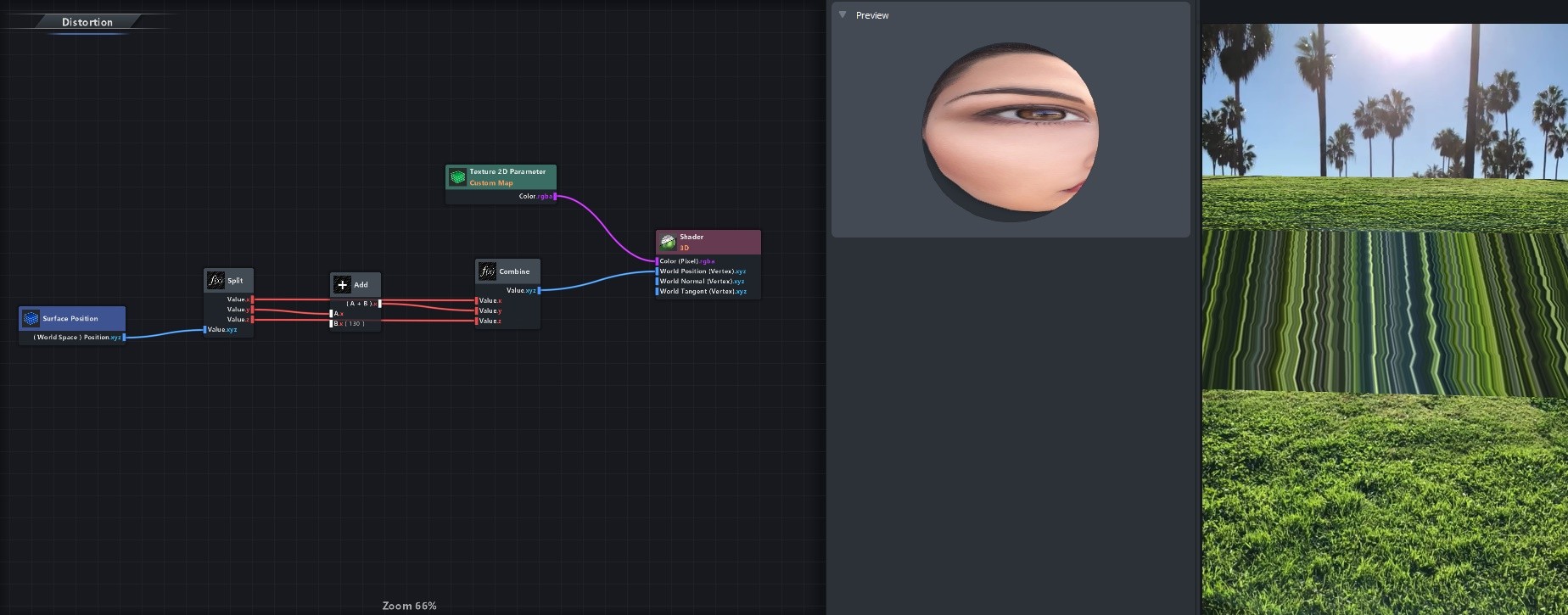
As you can see, the entire plane is going up and it is taking its contents along with it. Those squiggly stretching lines you see are just the last pixels of this material stretching all the way to the end of the plane, as it doesn’t know what those values are (the Device Camera Texture has reached its end at the bottom).
Get rid of the Add node, and grab a Voronoi Noise node instead! Throw the Surface Position in its Seed input, and multiply the noise by something like 100. You’ll now see these waves.
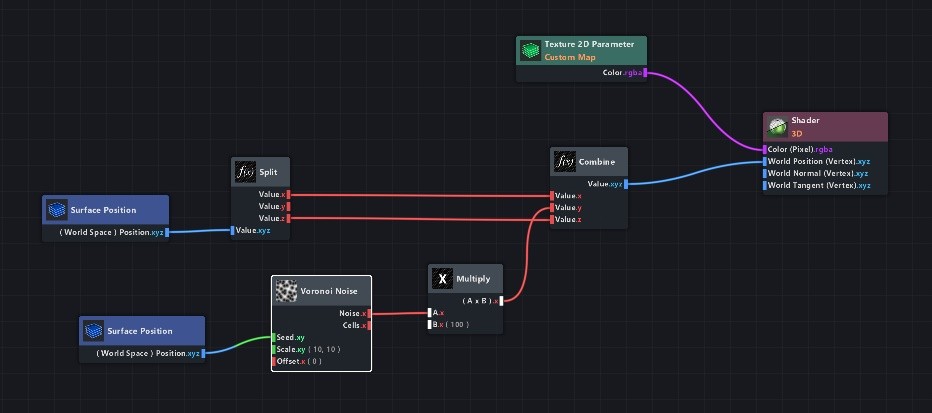
Why waves?
The world space position we’re using for the Voronoi Noise is xyz, while the seed input is only xy. This means the z information is not used for seeding the noise, and you can see that in those waves as they’re not changing in the z-axis (away/towards you)!
On the other hand, the Y axis is used, but is totally useless since the plane has the same Y value everywhere (it’s flat).
So we need to swap the y axis with the z axis before it goes into the Voronoi Seed input.
Grab another Combine node and wire it like this:
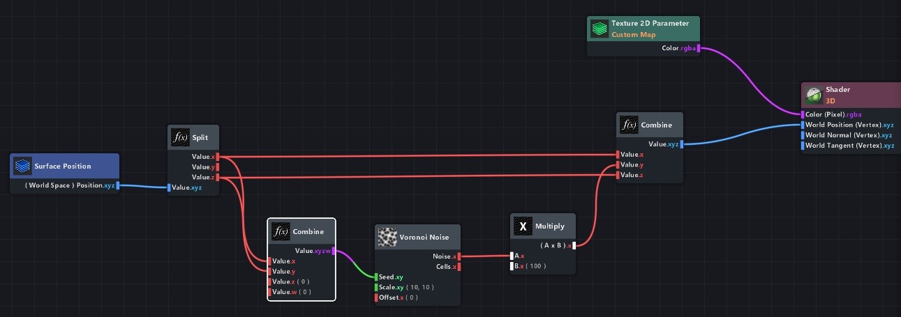
As you can see, I reused that Split node that was still there. No need for making a node if it already exists.
(Sidenote: you can also use the Swizzle node for this, instead of splitting/combining the channels. Set it to ‘xz’.)
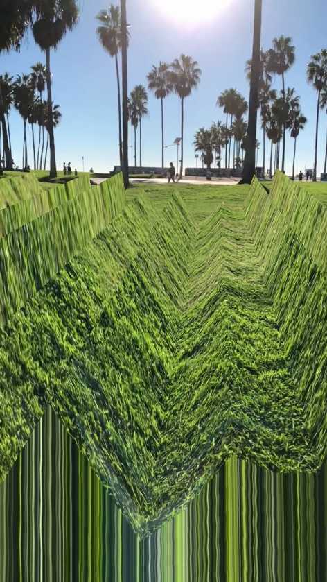
This channels the z output of the Surface Position to the y input of the noise seed (and it leaves x intact)! Now, the noise will be properly wavy:
Dial down the Multiply node a bit, and add an Elapsed Time node to the Offset input of the Voronoi Noise. This will make it animate, which looks way cooler.
The scaling of this noise is not right yet, though. By default the Voronoi Noise scale in the node is set to (10, 10), but because we’re working on quite a large scale I’d just go reduce it to something like 0.018. That looked right for me.
You can always plug the output of a node into the Color input of the Shader node to see what it looks like!
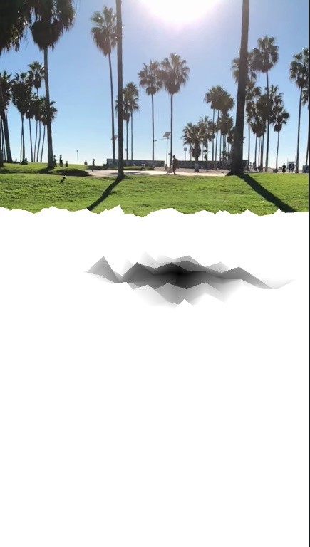
The only annoying thing is that there are no smooth edges. Because of that, you can still see this pixel stretching at the bottom, and the end of the plane is clearly visible.
To fix that, we need to tell the Voronoi Noise to smoothly lower its output value as it reaches an edge of the plane.
We can find the edges of the plane using a Surface Position node like the one we already made earlier, except you’ll need to make a new one as its ‘Space’ setting needs to be set to ‘Object’ this time (instead of ‘World’).
Plug it into the color of your shader to preview it – this is the data it is giving us:
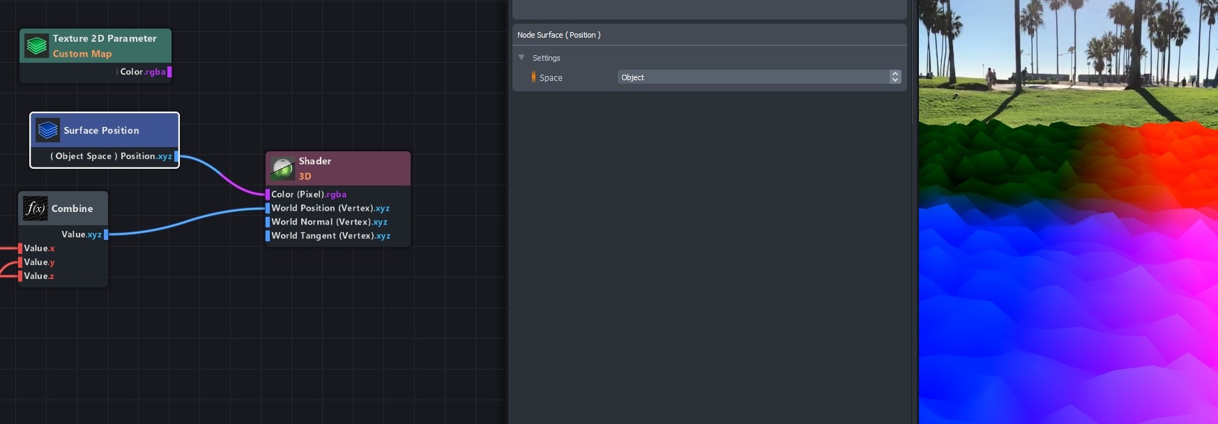
This is actually really useful, as it gives us a value of -1 to 1 in each direction.
Red -1 is left, Red 1 is right (x-axis).
Green -1 is down, Green 1 is up (y-axis).
Blue -1 is Near, Blue 1 is far (z-axis).
We don’t see the green one, as the plane is exactly at position 0 in height.
And the waves don’t count, because they’re calculated after this Surface Position node is getting its data.
In order to tell the noise to be at its strongest in the middle and weaker as it reaches the edges, we need to multiply the output of the noise by a shape on the plane that has a value of 1 in the middle and a value of 0 around the edges. Like a mask.
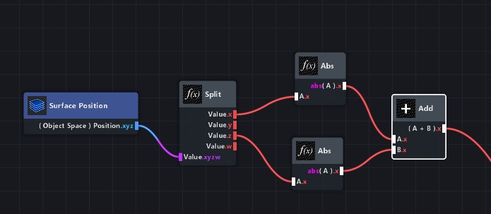
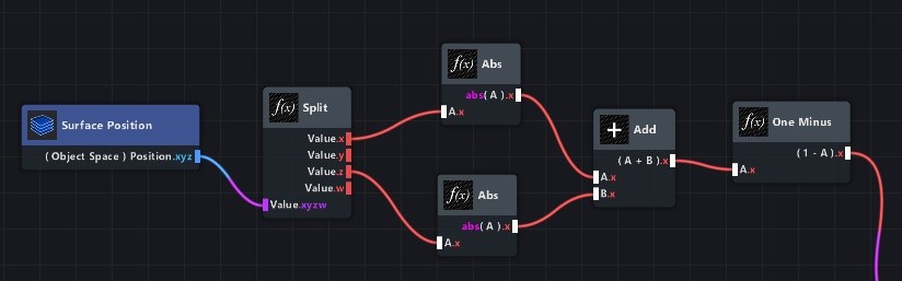
Believe it or not, but we’re actually almost there. Think about it this way: the red channel is already doing a smooth ramp towards the edge on the right. It’s just doing the same but in negative values on the left.
Split this Surface Position output into three different channels, and only plug the red into the color. Now, add an ‘Abs’ node in between. That already is a ramp going from 1 to 0 to 1, indicating edges from left to right!
That ramp on the left is nothing new, it’s just the negative values inversed so they’re above 0 and thus visible (which is what the Abs node does).
Now, do the same for the z channel (which is blue), and add them both together:
Look at that! The middle is dark, towards the edges it gets brighter! We could have also made a circle, or used a texture for the shape, but this seemed more helpful for the sake of this tutorial.
Since both edges (x and z) are overlapping, the values will get really bright (with values over 1).
Add another Add node to this, and set it to -1. That way, we can be sure that the maximum value will be 1.
(since, without the added -1, the maximum value of both edges combined is 1 + 1 = 2. And 2 minus 1 will get us back to 1.)
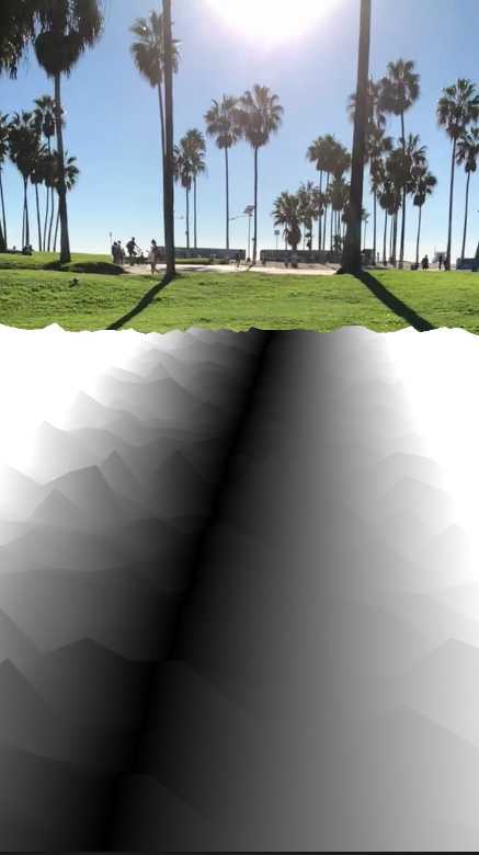
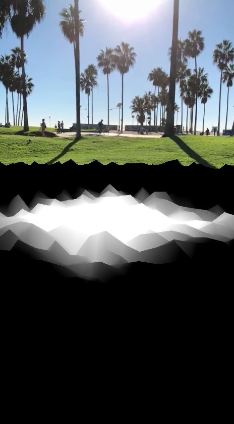
One last thing, the colors are inverted. White means higher values, which means more noise. And we want the most noise to be in the middle and not around the edges.
So add a ‘One Minus’ node (which is a node that does ‘1-x’) to invert these colors.
Now there’s white where the noise should be, and black where it shouldn’t be.
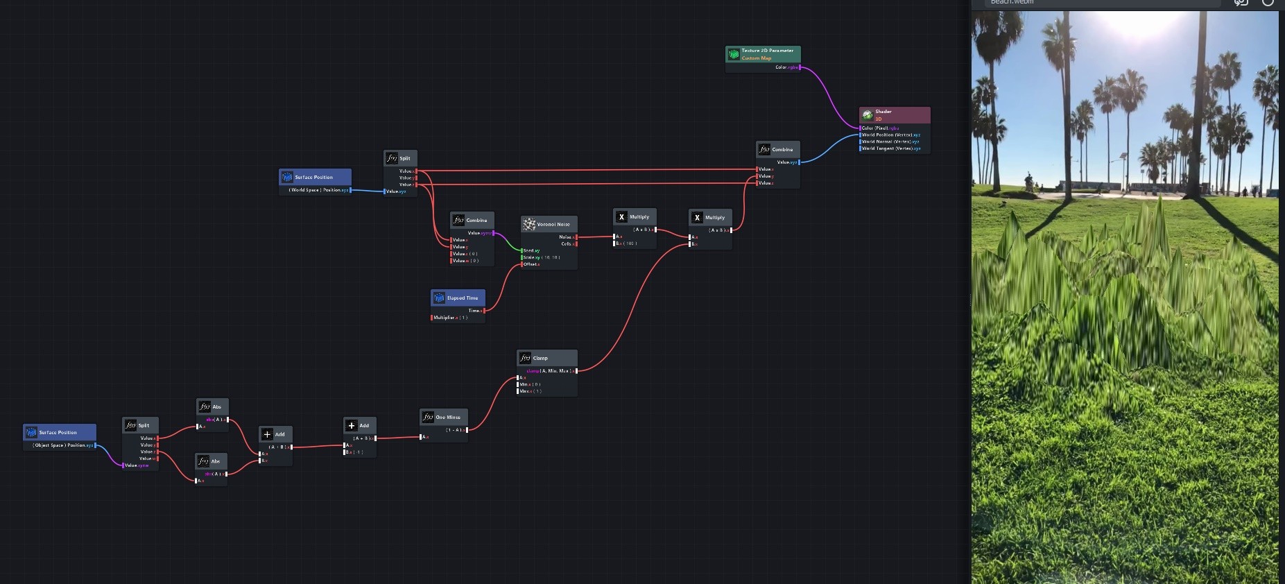
The output of the Texture node can be plugged back into the Color input of the Shader, and the One Minus node should be multiplied with the noise output.
Add a ‘Clamp’ node between the One Minus and the Multiply node, since the One Minus will probably create lots of negative values we can now simply cut off (which is what Clamp does).
You don’t need to change any settings of the Clamp node; it’s already set to clamping everything that’s not between 0 and 1.
This is our final graph, and the noise should now only be visible in the middle of the mesh!
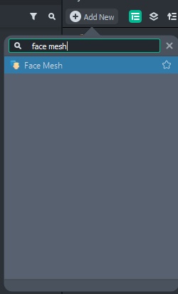
Face Mesh distortion
Now that we have looked at vertex displacement and UV projection, we can combine these two features with the new Face Mesh.
You can make weird face distortion effects like these with it:
This is built entirely using the same techniques as mentioned in Displacement and Projections, except the mesh is now the new Face Mesh object!
When working with the front facing camera and doing vertex displacements, make sure to add a Device Tracking component to your camera!
This will use the gyroscope to figure out the rotation of the phone.
![]()
The Face Mesh can be used like any other mesh, meaning the snap() function in JavaScript and the vertex displacement in the shader graph will both work!
The project files for this particular example (‘Face Glitch’, link to lens here) can be downloaded at the end of the page.
Triplanar noise & Voronoi on spheres
Click here to download the Triplanar Voronoi Noise subgraph and an example project.
Or keep reading to see how it is made, and why it is a good alternative to the built-in Triplanar Noise!
Spheres never have perfect UVs (because of the map projection problem, like with maps of planet Earth).
So, at some scale, there will always be an inaccuracy in the texture or shader you apply to it.
But an even bigger problem arises when using noises on spheres: The UVs of the mesh are not a closed loop, even though the mesh is.
Meaning, the UVs go from 0 to 1, and then somewhere on the mesh there’s a hard edge going back to 0 on the UVs.
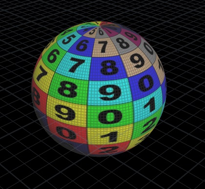
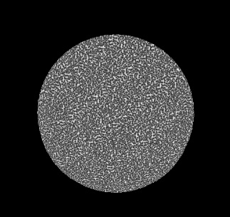
Which looks like this line:
(Image of a Lens Studio default sphere with Voronoi noise applied to it, using the Surface UV Coords as its seed.)
This is normal behaviour for spheres – they have to have a cut somewhere if you want the texture to not look stretched.
To better understand that, look at the UVs of a sphere:
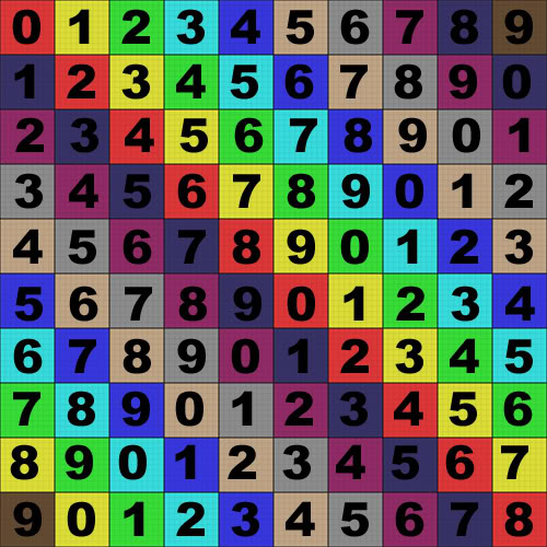
It might look good on the sphere, but at one point the numbers 7, 8, 9… have to go back to 0.
When generating a noise, it uses these UV coordinates to determine the noise shape – which means this cut back to 0 will show an edge.
So how do you add noise to a sphere?
The Triplanar Noise subgraph (used in some Material Library materials, like ‘Jello’) doesn’t seem to have this problem, but it is not working with Voronoi noises.
Instead, it uses the Simplex noise.
Let’s look at how this Triplanar Noise subgraph deals with the UV problem first, before we make a Triplanar Voronoi Subgraph!
The Triplanar Noise subgraph (screenshot below) uses the Object Space Surface position, so it ignores the UV coords entirely.
This is why there is no visible seam: the Object Space Surface Position is a gradient in all 3D directions that goes on forever. Not just 0 to 1 mapped to the mesh.
Then, it uses 3 different noise nodes to get a noise value for each direction (x, y, and z).
These are averaged (added together and divided by 3), in order to get the final value for this noise.
The problem with this approach is that in each individual direction, stretching will occur (because the noises are only projected from one plane each time).
This is what the three noises in the Triplanar Noise subgraph look like individually for respectively x, y, and z:
This means that, when the values are averaged, these stretches will not entirely disappear. They will still be in there, just less visible.
And the resulting values will be much softer and washed out, because every pixel is the average of three different values. This is the final Triplanar Noise output:
For the ‘Jello’ material in the Material Library, this is totally fine. But if you want to make a more stylized type of noise on a sphere, it will be pretty difficult to change the look of this.
Also, since the Simplex noise does not have an ‘offset’ value, the only type of animation you can do with it is a 3d translation. This can be done in all 3 directions, of course, but it still does not look as organic as the Voronoi offset.
This means the ‘Jello’ material is not really having an animated distortion – its distortion is static, but moving through space (all three noises individually, before being averaged together).
If you look at its noise, you can see it’s only doing these stacked translations blended together, and not an actual animation.
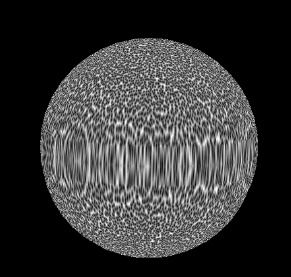
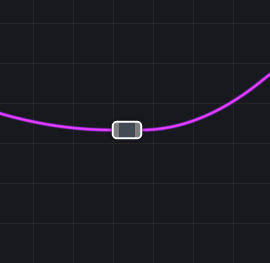
The first gif is of the Triplanar Noise, and the second one shows the Offset animation on a Voronoi noise:
The Voronoi has a much nicer distinct animation type to it, because the patches in the noise are moving individually. But then again, this Voronoi noise still has that line running through the sphere (on the backside of it), because of that UV problem.
So how do we get an animated Voronoi noise that’s actually seamless on the entire surface of the sphere, without stretching?
This is where that ‘offset’ value of the noise comes in handy.
We will project individual Voronoi noises onto the mesh from three axes,
using the offset for the remaining axis for every projection, and multiplying those results together. This will keep the shapes intact without stretching, and it will be seamless.
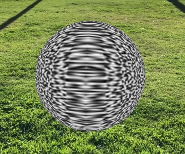
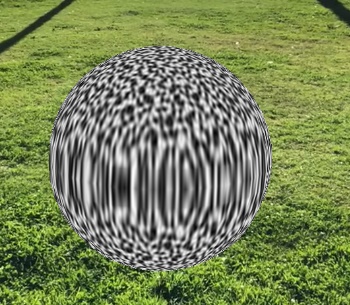
Before I start explaining that, let’s first look at the end result for this new, Voronoi-based, seamless noise on a sphere (two different scales):
As you can see, that typical Voronoi style is still in there.
It changed a bit because all three axes are multiplied together, but it still looks much more organic than the original Triplanar Noise.
Of course, the style you need is completely dependent on your project!
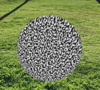
For comparison, this is the Triplanar Noise:
The Triplanar Voronoi subgraph I am going to be making here can also be downloaded at the bottom of the page, including an example project!
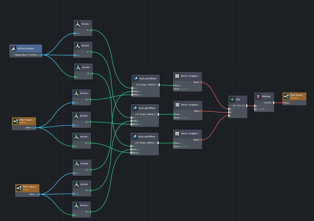
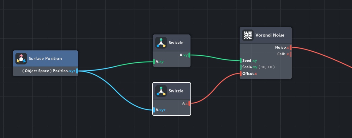
To start off, make three individual Voronoi Noises based on the Surface Position (object space) – make sure to use the Swizzle node to change the incoming seed axes for each of these noises.
This means, for the xy-plane, make a noise like this:
Do the same for the other two planes (xz and yz in the Swizzle), and check that the three individual noises look like this on the mesh:
To get rid of the stretching, the offset should be wired to the one axis not used for each noise.
So make another Swizzle and give it the one letter of ‘xyz’ that’s not in the first Swizzle:
This way, two axes will show a normal noise, and the third one will leave a trail of this noise in depth (which is what the offset does). This is best displayed on a cube:
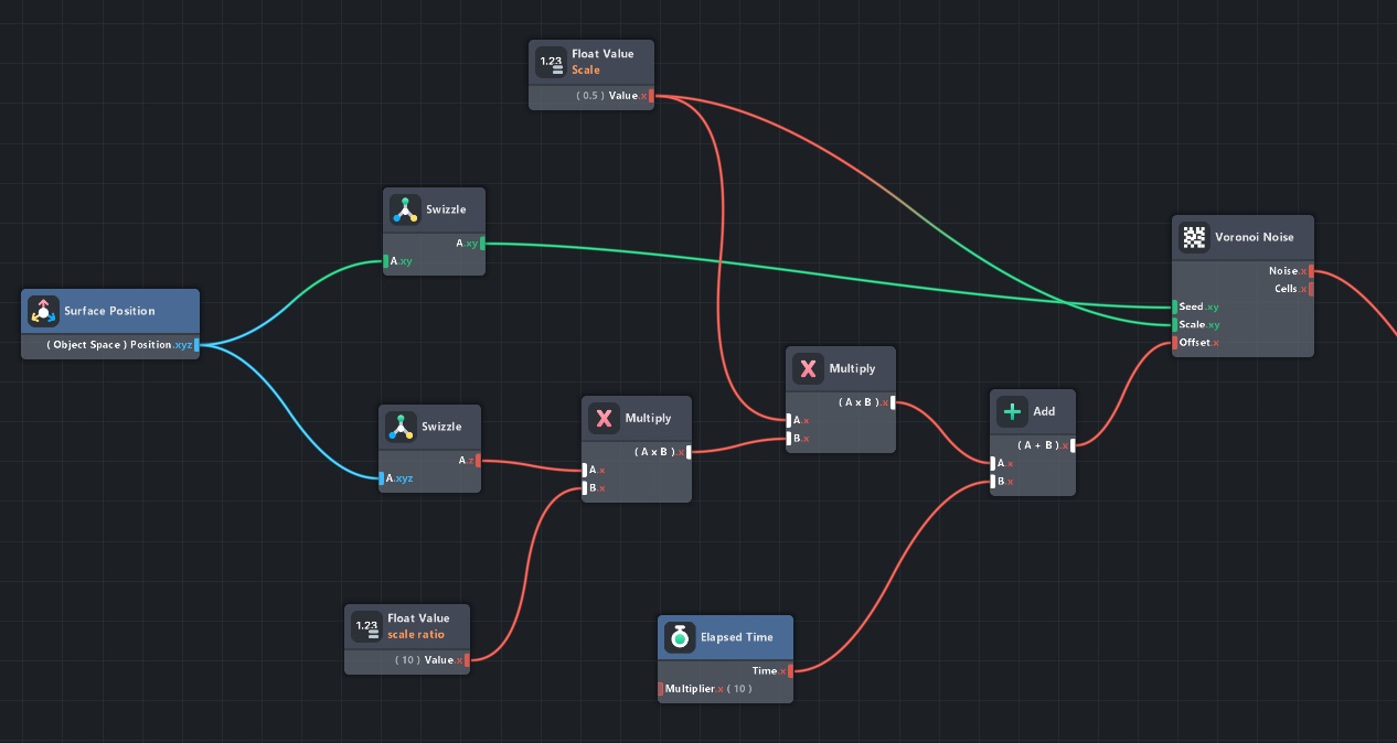
To get this animated result, make sure you add a Time Elapsed node to the value that goes into the Offset of the Voronoi noise. And set a custom Scale in the Voronoi noise.
Multiply the Offset input by the same value as the noise scale, but also multiply it with another value that makes it look less stretched. A factor of 10 is ideal.
This is what the graph looks like after these changes:
Now, we need to make this work in all three directions. Copy the Swizzles twice, plug them in the other two noises, and add random big numbers (like 1000 and 2000) to their seeds. This will make sure we don’t get any visible repetition.
Multiply the noises together, and that should be all! The graph is too big to show on a screenshot, but you can download the subgraph and check if out for yourself! (Example project + subgraph with comments!)
I also added some other features to it, like switching between seeing the noise or the cells output.
Here’s a demo of what the Triplanar Voronoi can do, applied to the vertex positions (along normals).
This Lens Studio project file is included in the downloads down below, as well as the subgraph file!
Useful tips & tricks
Oversight
Node graphs easily get messy. Here are some tips on keeping them under control:
If you have a lot of lines in one place, you can click and drag on the lines to make an ‘elbow’ in it! It’ll help with not getting everything tangled.
Use comments! It’s just like with programming – after a while, you won’t remember what everything was for, and you’ll really thank your past-self if they used comments.
You can make a comment via the TAB menu:
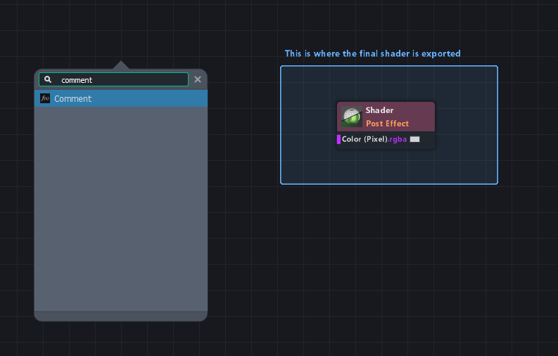
And always keep a lot of distance between nodes. Enough to be able to place another node in between them, without having to rearrange your whole graph at a later time.
Use ‘P’ to give a selected node a preview thumbnail.
Loop nodes
Loop nodes are a great way of telling the shader to do the same thing over and over again, and collecting all those results.
I’ve made a material that blurs an image using a Loop node, which is way too slow to actually use in real life.
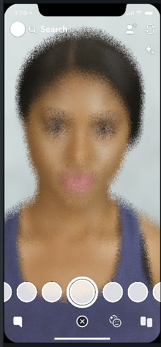
So what we’re about to do is totally useless, but it is a good demo for the Loop node. This will be the end result of this Post Effect:

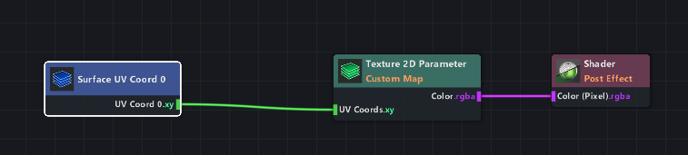
We need to start with a Shader (Post Effect), and a texture parameter.
You could also get a Screen Texture node instead of a Texture Parameter, and use the Texture Sampler to get the current texture from the screen. This way, it’d be a real Post Effect that applies the effect to whatever is underneath it. I have included this option in the download down below, but for now I’m going with a Texture Parameter.
Set the Texture coords to ‘Custom’! We’re going to mess those up a bit.
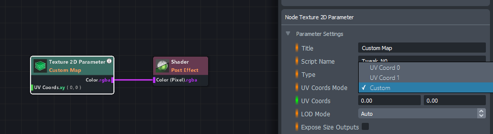
Coordinates are like the UV map in 3D models – they tell the material where to place the texture. So let’s give it a Surface UV Coord (0) node.
There also is a Surface UV Coord (1), but this is only used when you have alternative UVs in you mesh or something like that. Not important for now.
Search for a node called “Scatter Coords”. This will literally make a mess of your coordinates, which is kind of what we want. It already looks a little bit like a blur, except the displacement is way too sharp.
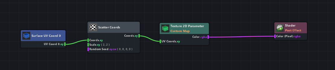
We basically want it to do this, but like 40 times. And then get the average. That’ll look like a blur, without the sharpness of the displaced pixels all over the image.
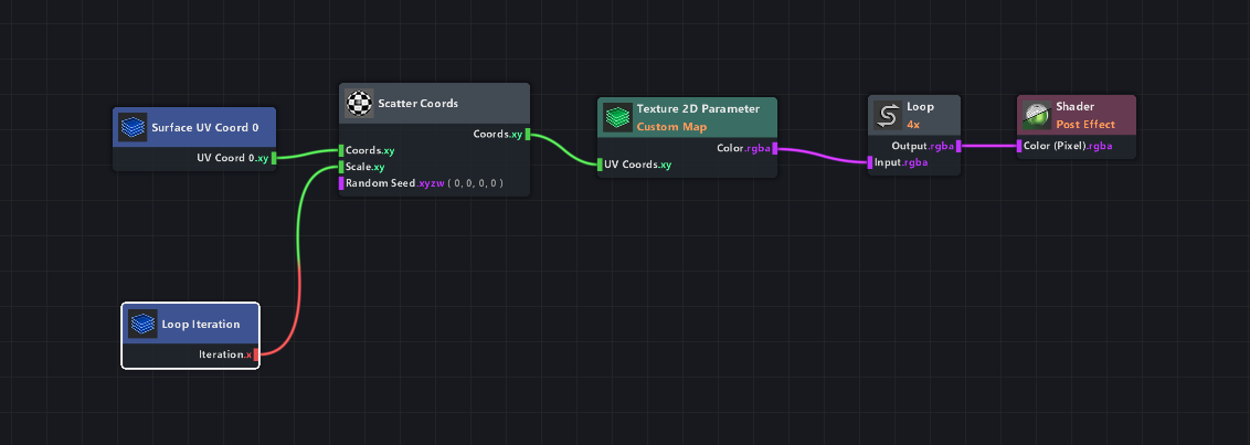
You could manually copy the whole setup 40 times and connect them all to a node that takes the average at the end, but that would be way too much work. The loop node is going to save time here – just add it after the Texture node, like so:
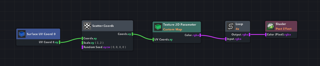
As you’ll see in the node settings, the Loop Mode is already set to ‘Average’ by default. And Iterations is set to ‘4’.
But something is still missing, since all 4 loops are exactly the same right now. We need it to make variations for each loop, which is what the Loop Iteration node is for.
Connect it to the Scale parameter of the Scatter Coords node.
This means that in the first loop, the Scatter Coords node will have a scale of 0. On the second loop, the scale will be 1. On the third, it’ll be 2. It’s adding one for each loop.
Add a Multiplier with a very low number (like 0.1) right after the Loop Iteration node to make the increments a lot smaller.
And connect the Loop Iterations to the Scatter Coords Seed input as well! We don’t want it to use the same seed for every loop.
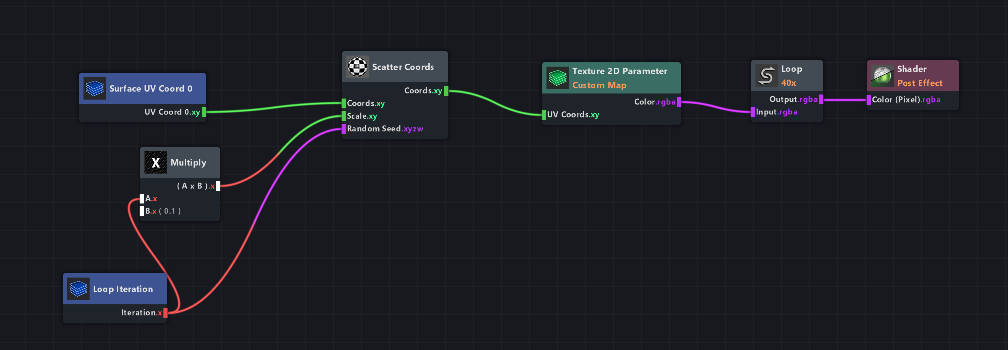
The last step is to increase the amount of loops! It will scatter the image just a little bit per loop and take the average of all loops, which means that the more loops you have the smoother it gets.
You can also change the scaling (that Multiply with a value of 0.1) to change the blur size.
For good blurring quality, it should loop at least 40 times. Which makes it way too slow for the average phone to run on. But hey, at least you now know how to use the Loop node.
Bool groups
If you’re working with Parameter nodes (which create UI elements in the Inspector to use), it’s nice to keep those user-friendly and clean.
A good way to categorise these parameters is by adding them to so-called Bool groups. This will only show the parameter when a certain bool is set to ‘true’, like so:
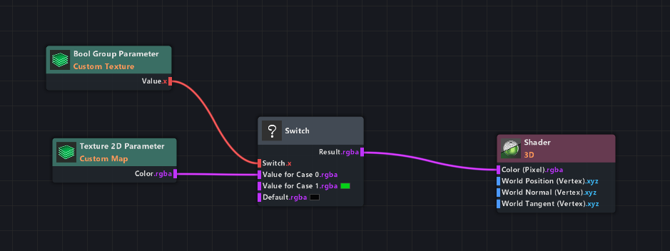
The Bool Group Parameter node (with the title “Custom Texture”) drives the Switch node, and the Texture 2D Parameter is set to this bool group.
Which means that, when the user has disabled the checkbox, the texture input will be hidden.


Downloads


